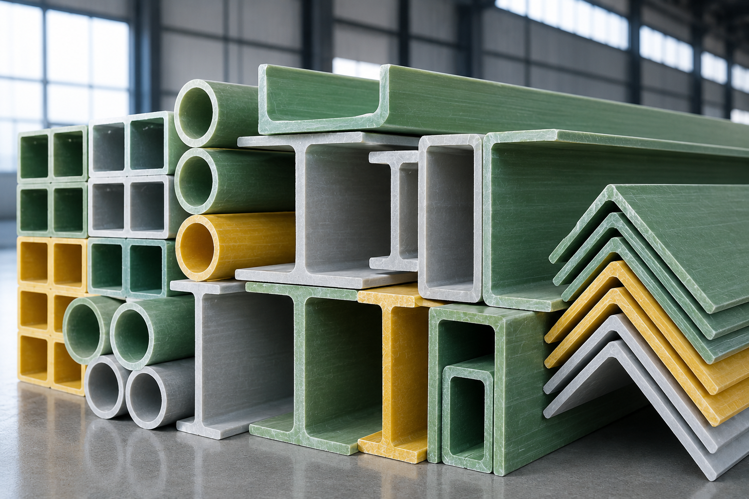
Pultruded FRP Angle vs Channel Strength Uses and Selection
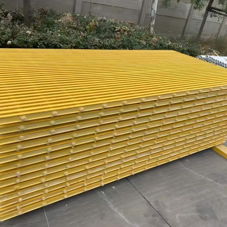
Compare pultruded FRP angle vs channel profiles including strength weight corrosion resistance applications and selection tips
Understanding Pultruded FRP Structural Profiles
What is a Pultruded FRP Angle (L-Shape)?
A pultruded FRP angle is an L-shaped structural profile characterized by two legs intersecting at a rigid 90-degree angle. Designed primarily for stabilizing assemblies and joining major load-carrying components, it delivers superior directional strength along its longitudinal axis.
-
- Configurations: Available in both equal leg angle and unequal leg angle dimensions to accommodate varied spatial constraints.
- Primary Roles: Extensively used for corner reinforcement, ledger angles, cross-bracing, kick plates, and structural connections.
- Key Advantage: Compact geometry that offers high tensile and compressive strength while remaining easy to fabricate and handle on job sites.
What is a Pultruded FRP Channel (C-Shape & U-Shape)?
A pultruded FRP channel features a broad web flanked by two parallel flanges, forming a distinct C-shape or U-shape. This geometry yields a high moment of inertia, enabling the profile to handle substantial bending loads and structural stresses.
-
- Geometry: Features a flat web base with perpendicular flanges, optimizing structural performance for horizontal beam applications and vertical column arrangements.
- Primary Roles: Widely specified for stair stringers, framework rails, equipment support bases, and secondary beam runs.
- Key Advantage: Outstanding flexural rigidity along the primary bending axis, making the profile an efficient, direct structural steel replacement.
The Pultrusion Manufacturing Process & Material Composition
The reliability of these GFRP profiles stems directly from the pultrusion process—a continuous, automated manufacturing method that pulls raw structural fibers through liquid resin baths and heated steel dies to cure them into exact profiles.
| Component | Material Type | Functional Contribution |
|---|---|---|
| Longitudinal Roving | Continuous E-Glass filaments | Delivers exceptionally high tensile and flexural strength along the length |
| Transverse Reinforcement | Continuous Filament Mat (CFM) | Provides critical crosswise strength and prevents delamination under load |
| Resin Matrix | Isophthalic Polyester or Vinyl Ester | Bonds fibers, transfers load, and ensures comprehensive corrosion resistance |
| Surfacing Veil | Synthetic polyester veil | Forms a resin-rich exterior layer to block UV rays, water ingress, and surface wear |
This uniform matrix distribution ensures consistent wall thicknesses, tight dimensional tolerances, and permanent resistance to aggressive industrial chemicals and marine atmospheres.
Key Differences: Pultruded FRP Angle vs Channel
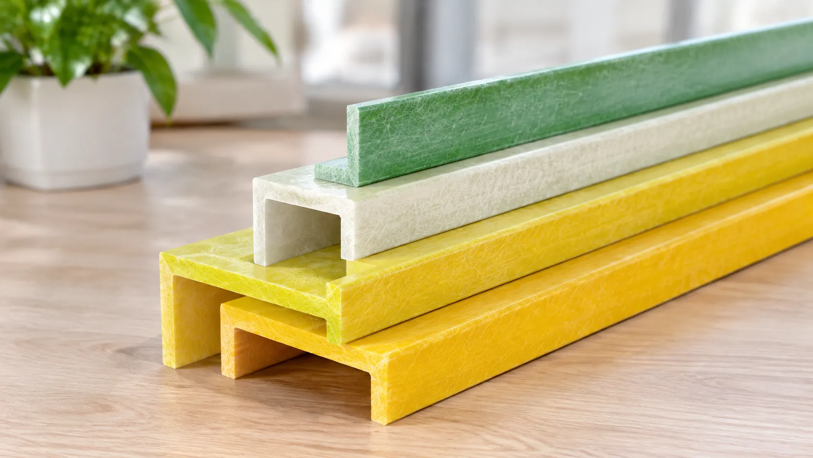
When designing lightweight, corrosion-proof frameworks, choosing between a pultruded FRP angle and a channel comes down to structural geometry, load paths, and how each profile manages bending and twisting forces. While both share the same continuous glass-fiber composite core, their cross-sections dictate entirely different roles on the job site.
Cross-Sectional Geometry and Structural Design
An FRP angle features an L-shaped cross-section with either an equal leg angle or unequal leg angle design. This geometry creates a single 90-degree corner that makes it exceptionally easy to nest against flat surfaces, bolt across perpendicular planes, or use as an edge cap. However, because an angle lacks symmetry across its principal axes, applied loads easily induce coupled bending and twisting.
An FRP channel (typically a C-shape or U-channel design) consists of a solid central web flanked by two parallel flanges. This geometry creates a single axis of symmetry. The opposing flanges act as compression and tension flanges under vertical loads, distributing mechanical stresses across a deeper profile depth. For detailed cross-sectional specifications, our selection guide for FRP pultruded profiles breaks down standard wall dimensions and resin pairings.
Load-Bearing Capacity and Flexural Rigidity
Channels substantially outperform angles in flexural load bearing capacity when loaded parallel to the web:
-
- Bending Resistance: A C-channel places high-strength unidirectional roving far from the neutral axis within its twin flanges, delivering a high moment of inertia ($I_x$). It resists sagging and bending over moderate-to-long horizontal spans.
- Axial and Transverse Forces: FRP angles possess lower flexural rigidity along their primary planes. While an angle can carry substantial axial tension or compression as a truss member or diagonal brace, it deflects quickly when subjected to primary mid-span transverse bending loads.
Torsional Resistance and Deflection Limits
Because both angles and channels are open structural profiles, neither matches the torsional resistance of closed rectangular tubes. However, their real-world performance under lateral and eccentric loads differs noticeably:
-
- Shear Center Mismatch: In an FRP angle, the shear center sits at the intersection of the two legs. Applying a load anywhere else causes immediate twisting along the member length.
- Twist Under Load: A C-channel has its shear center positioned behind the web, outside the physical section. While eccentric loading requires web stiffeners or bracing to prevent rotation, a channel loaded symmetrically through its web flange planes maintains tighter deflection limits and resists lateral-torsional buckling far better than an angle.
Weight and Material Efficiency Comparison
Channels use material more effectively for horizontal spanning and primary framing, whereas angles offer maximum material efficiency for connections, shelf ledges, and tie-ins.
| Performance Metric | Pultruded FRP Angle (L-Profile) | Pultruded FRP Channel (C-Profile) |
|---|---|---|
| Cross-Section Type | Asymmetric open profile (L) | Mono-symmetric open profile (C/U) |
| Major Axis Bending Efficiency | Low to Moderate | High |
| Torsional Resistance | Low (twists under off-center loads) | Moderate (stable under web-aligned loads) |
| Primary Structural Mode | Tension ties, bracing, edge support | Beams, joists, stair stringers |
| Weight-to-Stiffness Ratio | Optimized for compact connections | Optimized for unsupported linear spans |
| Installation Footprint | Low clearance, fits flush against corners | Requires web-and-flange clearance |
For short brackets, stiffeners, and edge cladding, angles eliminate redundant material and keep assembly weights low. When bridging open spans under heavy foot traffic or equipment weight, channels deliver the necessary section modulus while keeping total poundage well below structural steel.
Shared Benefits of Pultruded FRP Angles and Channels
When comparing a pultruded frp angle vs channel, the difference comes down to geometry and load distribution. However, both shapes share the core material performance that makes glass-reinforced polymer (GFRP) the modern standard for harsh environments. We manufacture both profiles to eliminate the structural weaknesses and high maintenance costs typical of mild steel, stainless, and aluminum.
| Performance Metric | Pultruded FRP Profiles | Structural Mild Steel | Structural Aluminum |
|---|---|---|---|
| Corrosion Resistance | Excellent (Acids, Salts, Alkalis) | Poor (Requires Coating) | Moderate (Pits in Chlorides) |
| Weight | ~1.8 g/cm³ | ~7.85 g/cm³ | ~2.7 g/cm³ |
| Electrical Conductivity | Non-Conductive (Insulator) | High Conductor | High Conductor |
| Thermal Expansion | Very Low | Moderate | High |
| Field Modification | Easy (Standard Carbide Tools) | Requires Torch / Hot Permit | Moderate (Specialized Blades) |
High Corrosion and Chemical Resistance
Traditional metals degrade quickly when exposed to chemical splash, constant moisture, and saltwater. Both our FRP angles and channels feature high-grade resin matrices that encapsulate the inner glass fibers, sealing them against environmental attack.
-
- Immunity to Rust: Neither profile will oxidize, peel, or rust, even in coastal installations.
- Aggressive Environments: They serve as reliable framework elements alongside frp grating for chemical plants and wastewater facilities where acid fumes destroy steel in months.
- UV Stability: Formulated with synthetic surfacing veils and UV inhibitors to prevent fiber bloom in full outdoor sun.
Exceptional Strength-to-Weight Ratio
Our pultruded structural shapes deliver reliable load bearing capacity at roughly one-quarter the weight of structural steel:
-
- Pound-for-Pound Strength: Continuous rovings provide high longitudinal tensile and flexural strength.
- Rapid Installation: Lightweight sections allow small crews to erect frames, catwalk supports, and brackets manually, eliminating the need for expensive mobile cranes.
- Lower Freight Costs: Moving bulk GFRP profiles to remote job sites requires fewer trucks and reduces logistical overhead.
Electrical Non-Conductivity and Thermal Insulation
Safety is a core driver for selecting composite structural profiles. Both shapes provide essential passive protection:
-
- Dielectric Safety: High dielectric strength makes these sections completely non-conductive, eliminating the need to ground frames in electrical substations, mass transit lines, and switchgear enclosures.
- Thermal Barrier: The extremely low thermal conductivity of glass-fiber composites prevents thermal bridging in structural envelopes and modular cold storage framing.
- EMI/RFI Transparency: They do not distort radio frequencies or magnetic fields, making them suitable for radar and communication towers.
Low Maintenance and Extended Service Life
Steel requires repeated sandblasting, priming, and painting throughout its operating life. Pultruded profiles are colored through-and-through during production, meaning scratches do not expose a vulnerable base layer.
Aside from standard visual inspections and straightforward upkeep—similar to the practices outlined in our guide on the care and maintenance of frp grating for longer service life—these sections remain structural and operational for decades without recoating or galvanic treatments. This translates directly to the lowest lifecycle cost of any structural material on the market.
Primary Application Scenarios
When deciding between a pultruded frp angle vs channel, matching the profile to the specific structural demand makes all the difference in cost, safety, and performance. Both serve as a modern structural steel replacement, but their geometric shapes dictate completely different installation roles across industrial platforms and frameworks.
When to Use FRP Angles: Framing, Bracing, and Corner Trim
We rely on pultruded FRP angles primarily for secondary structural support, stability bracing, and protective edge trim. The equal leg angle and unequal leg angle designs make them exceptionally versatile for lightweight connections:
-
- Cross-Bracing and Trusses: Pultruded angles handle tension and light compression well, stabilizing larger frameworks against lateral sway.
- Grating Ledger Angles: An angle fastened along concrete walls provides a reliable, level perimeter shelf to support walkway panels.
- Corner Guards and Transitions: Because GFRP profiles do not dent or corrode like aluminum or steel, angles shield concrete curbs, tank edges, and wall corners from heavy impact.
- Light Equipment Framing: Ideal for constructing lightweight enclosures, electrical rack mounts, and protective machine guards.
When to Use FRP Channels: Support Beams, Stair Stringers, and Structural Frames
Pultruded FRP channels (both C-channel and U-channel designs) are our go-to choice when a project calls for substantial bending strength and one-directional load support. Their stiff web and dual flanges carry dynamic loads that would easily twist an angle profile:
-
- Stair Stringers and Handrail Kicks: Structural C-channels form the backbone of industrial safety stairways, holding treads securely in place.
- Secondary Floor Beams: When used alongside heavy-duty FRP I-beams, channels serve as cross-joists beneath elevated walkways and access platforms.
- Catwalk Foundations: Channel webs create a solid boundary frame capable of supporting heavy spans of FRP grating panels under high pedestrian and cart traffic.
- Equipment Skids and Sub-Bases: The flat mounting base of channels allows pumps, tanks, and electrical cabinets to sit flush without rocking.
Industry Uses: Chemical Plants, Marine, Utilities, and Water Treatment
Both angles and channels replace failure-prone metal in aggressive environments where corrosion destroys standard structural steel:
-
- Chemical Processing Plants: Acidic fumes, caustic washdowns, and solvent vapor quickly compromise galvanized steel. Our pultruded profiles withstand continuous chemical exposure without pitting, rusting, or degrading.
- Marine and Offshore Facilities: Salt spray, tidal immersion, and high humidity destroy carbon steel. FRP channels and angles thrive on docks, offshore rigs, and coastal walkways without requiring protective re-coating.
- Water and Wastewater Treatment: Hydrogen sulfide gas and constant moisture create an aggressively corrosive atmosphere around clarifiers, digesters, and screen basins, where fiberglass framing profiles routinely deliver decades of zero-maintenance service.
- Power Utilities and Substations: Thanks to their non-conductive properties, these profiles provide safe access platforms, ladder rails, and transformer screens in high-voltage electrical fields.
Structural Connection and Fabrication Guidelines
Working with fiberglass structural profiles is straightforward, but it requires a different mindset than traditional steel fabrication. When joining a pultruded FRP angle vs channel, mechanical properties dictate specific joint details to maintain strength, prevent delamination, and maximize service life.
Bolting and Mechanical Fastening Methods
Bolting is our primary method for assembling GFRP profiles in the field. Because composite materials are anisotropic, bolt placement requires strict adherence to geometry rules:
-
- Hardware Selection: Always use 316 stainless steel bolts, nuts, and wide washers to match the corrosion resistance of the composite profiles.
- Edge Distance: Keep bolt holes at least 3 times the bolt diameter from any sheared or cut edge.
- Bolt Spacing: Maintain a minimum center-to-center pitch of 4 to 5 times the bolt diameter along the line of stress.
- Torque Control: Do not over-torque. Use calibrated torque wrenches with wide flat washers to distribute compressive loads evenly across the profile flange or web, preventing surface crushing.
When joining an FRP angle to a channel web or connecting components to primary members like heavy-duty FRP I-beams, structural clip angles provide rigid, reliable load transfer without introducing excessive localized stress.
Adhesive Bonding and Joint Detailing
Adhesive bonding creates continuous load paths and eliminates stress concentrations caused by drilled holes. We frequently combine chemical bonding with secondary mechanical fasteners for maximum joint integrity in corrosive environments.
| Joint Factor | Best Practice | Technical Objective |
|---|---|---|
| Surface Prep | Mechanical abrading (80-grit) + solvent wipe | Removes surface sheen and exposes glass fibers |
| Adhesive Choice | Two-part structural epoxy or polyurethane | Matches flexural modulus and thermal movement |
| Bondline Thickness | Maintain 0.5 mm to 1.5 mm thickness | Prevents adhesive starve-out under clamping load |
| Edge Sealing | Exterior bead of resin or sealant | Stops moisture ingress and edge delamination |
Adhesive-only joints excel in shear load transfer, making them ideal for reinforcing flat-to-flat surfaces such as equal leg angle attachments inside channel flanges.
Fabrication, Cutting, and Hole Drilling Best Practices
Fabricating pultruded FRP profiles on-site does not require hot-work permits, torches, or heavy machinery. Standard wood and metalworking tools work well when equipped with the right cutting edges:
-
- Cutting Tools: Use diamond-grit circular saw blades or carbide-tipped blades (60 teeth or more). High blade speeds prevent splintering and ragged edges on channel legs and angle edges.
- Drilling Precision: Use carbide-tipped drill bits or specialized composite spade bits run at moderate speeds. Support the back of the flange with wood or composite scrap to prevent breakout on the exit side.
- Edge Sealing: Coat all newly cut ends and drilled holes immediately with a compatible catalyzed polyurethane or vinyl ester resin. This seals exposed glass fibers against chemical wicking and water absorption.
- Safety Protocols: Always operate localized dust extraction and mandate P2/N95 respirators, safety glasses, and gloves during fabrication to protect workers from fine glass dust.
How to Select the Right FRP Profile for Your Project
Choosing between a pultruded FRP angle vs channel comes down to your project’s load vectors, environmental severity, and geometry. We evaluate structural framing systems based on three core technical factors to ensure the selected profile delivers maximum structural safety and cost efficiency.
Evaluating Structural Load Requirements and Deflection Limits
When sizing fiberglass structural profiles, deflection—rather than ultimate fiber stress—usually governs the design. Pultruded fiberglass has a lower modulus of elasticity than carbon steel, meaning flexural stiffness must be engineered through geometry.
-
- Primary Flexural Loads: Choose an FRP C-channel when the member must support direct bending loads over a span. The dual flanges and vertical web provide a significantly higher moment of inertia ($I_x$) than an angle of comparable weight, keeping span deflection within standard $L/240$ or $L/360$ limits.
- Secondary Loads and Bracing: Select equal leg or unequal leg FRP angles for continuous edge support, ledger angles, cross-bracing, or tension ties. Angles excel under axial tension and secondary shear, but deflect excessively when used as unsupported, single-member horizontal beams.
Selecting Resin Formulations (Isophthalic Polyester vs. Vinyl Ester)
The mechanical capacity of an FRP profile depends on the continuous glass rovings and mats, while the resin matrix dictates its chemical durability and temperature thresholds. We produce our pultruded profiles in two primary resin formulations to match specific operating conditions:
| Feature / Metric | Isophthalic Polyester (ISO-FR) | Vinyl Ester (VE-FR) |
|---|---|---|
| Corrosion Performance | Excellent for splash zones, water, mild acids, and general industrial sites | Superior resistance to strong acids, caustics, chlorine, and organic solvents |
| Max Service Temperature | Up to 150°F (65°C) | Up to 200°F (93°C)+ |
| Flame Spread Rating | ASTM E84 Class 1 (Flame spread 25 or less) | ASTM E84 Class 1 (Flame spread 25 or less) |
| Cost Profile | Economical, standard commercial grade | Premium performance grade |
For standard access platforms, pairing ISO-FR channel stringers with standard components such as an FRP grating standard size walkway panel provides the ideal balance of chemical resistance and structural economy. In high-temperature pickling baths or severe chemical processing facilities, upgrade directly to vinyl ester.
Navigating Standard Dimensions, Wall Thicknesses, and Tolerances
Pultruded profiles adhere to strict manufacturing standards such as ASTM D3917 and EN 13706. To ensure seamless on-site fitment, verify profile cross-sections early in design:
-
- Channel Dimensions: Ranging from 2″ × 9/16″ up to 12″ × 3″ depths, channels feature a uniform wall thickness across the web and flanges, preventing localized stress concentrations common in tapered structural steel channels.
- Angle Profiles: Available in both equal-leg (e.g., 2″ × 2″ to 6″ × 6″) and unequal-leg configurations. Ensure the selected wall thickness (commonly 1/4″ to 1/2″) satisfies minimum edge-distance bolting criteria.
- Dimensional Tolerances: Factory pultrusion produces low dimensional variance, but always account for thermal expansion differentials (approx. 1.4 × 10⁻⁵ in/in/ °F) when interfacing FRP members with concrete or steel structures.
Frequently Asked Questions (FAQ)
Is a pultruded FRP channel stronger than an FRP angle?
In major-axis bending and horizontal spanning, a channel is significantly stronger and stiffer than an angle. When comparing a pultruded FRP angle vs channel of identical wall thickness and outer dimension, the channel delivers a much higher moment of inertia thanks to its dual flanges and structural web. While we use angles primarily to handle tension bracing, corner connections, or localized shear, our structural C-channels are built to resist higher primary bending moments and resist lateral deflection across open spans.
Can FRP profiles directly replace structural steel channels and angles?
Yes, but you cannot simply swap them out on a one-to-one dimensional basis without checking deflection limits. While pultruded fiberglass structural profiles easily match or exceed the ultimate tensile strength of standard carbon steel, GFRP has a lower modulus of elasticity (roughly one-sixth to one-fifth that of steel). As a result, designs are typically governed by stiffness and deflection rather than sheer yield strength. When we assist clients with structural steel replacement, we usually compensate by specifying a deeper web profile, thicker walls, or shorter unsupported spans to match the required structural stiffness.
How do FRP angles and channels perform in fire and high-temperature conditions?
Standard polyester formulations begin losing mechanical stiffness at temperatures above 150°F (65°C). For applications requiring elevated thermal performance, we manufacture our profiles using fire-retardant vinyl ester or halogen-free resin matrices meeting ASTM E84 Class 1 flame spread ratings (index of 25 or lower). These formulations integrate antimony trioxide or alumina trihydrate synergists that cause the material to self-extinguish as soon as an open flame source is removed, preventing flame propagation across industrial structures.