FRP I Beams Sizes Span Capability and Structural Selection
Discover FRP I Beam sizes span capability load limits key properties and structural selection for corrosion resistant industrial applications
What Is an FRP I-Beam? Overview and Key Properties
An FRP (Fiberglass Reinforced Polymer) I-beam is a high-performance fiberglass beam engineered to deliver superior structural stability in demanding industrial settings. Formed with an optimized I-shaped cross section, this composite member delivers high stiffness along its major axis while substantially reducing overall structure deadweight.
As specialized pultruded structural profiles, FRP I-beams serve as direct replacements for structural steel, aluminum, and timber across harsh environments where moisture, chemical fumes, and harsh operating conditions rapidly compromise traditional materials.
Pultrusion Manufacturing Process
FRP I-beams are produced using continuous pultrusion, a precision composite manufacturing method ensuring consistent dimensional tolerances and repeatable material performance:
Continuous Reinforcement: High-strength glass rovings provide longitudinal tensile performance, while continuous filament mats supply transverse shear stability.
Resin Wet-Out: Reinforcement strands pass through a resin bath utilizing targeted formulations, such as isophthalic polyester or vinyl ester systems, for targeted environmental resilience.
Thermal Curing: The saturated fibers are pulled through a precision-machined heated steel die, cross-linking the polymer into an ultra-dense, homogeneous cross section.
Automated Sizing: The continuous profile exits the die fully solidified and is cut to exact operational lengths with clean, square-cut finishes.
Key Mechanical and Structural Properties
The hybrid combination of high-density glass fibers and protective resin matrices grants these profiles exceptional mechanical capabilities:
Exceptional Load Bearing Capacity: Delivers high structural flexural strength, supporting significant uniform and point loads without permanent deformation.
Superior Corrosion Resistance: Zero risk of rust, scaling, or rot when exposed to acids, alkalis, salts, and high humidity.
Electrical and Thermal Insulation: Non-conductive properties eliminate grounding requirements and provide worker safety around high-voltage equipment.
High Strength-to-Weight Ratio: Weighs approximately 70% less than standard carbon steel, drastically cutting shipping logistics and lifting equipment costs.
Dimensional Stability: Low thermal expansion and zero moisture absorption ensure long-term geometric integrity.
FRP I-Beam vs. H-Beam Structural Profiles
Selecting the correct structural geometry between an I-beam and a wide-flange H-beam depends on load distribution and structural framing requirements:
Structural Feature FRP I-Beam FRP H-Beam (Wide Flange)
Cross-Section Profile Narrower flanges with a deep central web Flange width is generally equal to web height
Primary Structural Role Flexural framing, floor joists, roof purlins Structural columns, heavy multi-axis frames
Load Orientation Unidirectional vertical load bearing Multi-directional and lateral load resistance
Weight Efficiency Maximum vertical stiffness per unit weight Higher lateral torsional stiffness
Standard FRP I-Beam Sizes and Dimensions
We supply pultruded structural profiles engineered to direct dimensional standards, ensuring straightforward replacement or integration alongside legacy steel frameworks. Sizing structural fiberglass beams requires matching the web height, flange width, and component thicknesses directly to structural load bearing requirements.
Common Metric and Imperial Sizes
Our production lines supply FRP I-beams in standard imperial structural designations alongside standard metric dimensions. Standard web depths typically range from 100 mm (4 inches) up to 300 mm (12 inches).
The table below outlines common dimensional profiles regularly used in industrial framing:
Imperial Size (Depth × Flange × Thickness) Metric Equivalent (D × B × t) Typical Linear Weight (kg/m) Typical Linear Weight (lb/ft)
4″ × 2″ × 1/4″ 102 × 51 × 6.4 mm 2.53 kg/m 1.70 lb/ft
6″ × 3″ × 1/4″ 152 × 76 × 6.4 mm 3.90 kg/m 2.62 lb/ft
6″ × 3″ × 3/8″ 152 × 76 × 9.5 mm 5.65 kg/m 3.80 lb/ft
8″ × 4″ × 3/8″ 203 × 102 × 9.5 mm 7.44 kg/m 5.00 lb/ft
8″ × 4″ × 1/2″ 203 × 102 × 12.7 mm 9.67 kg/m 6.50 lb/ft
10″ × 5″ × 1/2″ 254 × 127 × 12.7 mm 12.65 kg/m 8.50 lb/ft
12″ × 6″ × 1/2″ 305 × 152 × 12.7 mm 15.63 kg/m 10.50 lb/ft
Flange and Web Dimension Specifications
Structural reliability depends on uniform wall thickness throughout both the web and the flanges. Unlike cast or hand-laid parts, our pultrusion process pulls continuous roving and matting through heated steel dies, maintaining tight structural tolerances across the entire run.
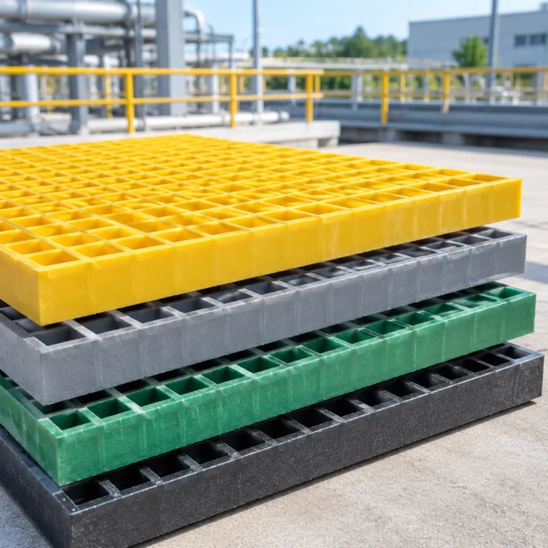
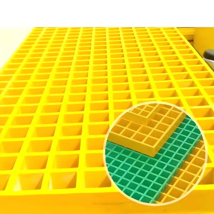
Flange Width (B): Proportioned to control lateral-torsional buckling while offering a stable bearing seat for secondary supports or platform layouts incorporating FRP grating standard size panels.
Web Height (D): Delivers the depth required to govern flexural bending resistance across primary spans.
Thickness (t): Pultruded beams generally feature equal thickness across the web and flange, eliminating stress concentrations at the interior radii and providing uniform thread engagement for bolted hardware.
Weight per Meter and Section Properties
Selecting the correct fiberglass beam demands balancing linear weight against key section properties, including the second moment of area (Ix) and section modulus (Sx).
Low Self-Weight: An FRP I-beam weighs roughly 75% less than a steel beam of comparable external dimensions, reducing dead-load calculations significantly.
Moment of Inertia (Ix & Iy): FRP has a lower modulus of elasticity than carbon steel, meaning structural designs are usually deflection-driven. Evaluating Ix ensures allowable service limits are met under full design loads.
Section Modulus (Sx): Governs allowable bending stress. The high longitudinal tensile strength of pultruded glass rovings ensures peak structural capacity without adding unnecessary weight to the support structure.
FRP I-Beam Span Capability and Load Performance
Calculating the span capability of an FRP I-beam requires a different engineering approach than traditional structural steel. While steel design often focuses purely on yielding, structural fiberglass beams are typically governed by stiffness and deflection. Understanding how these pultruded structural profiles behave under sustained load bearing conditions ensures your installation remains safe, rigid, and durable over decades of service.
Allowable Uniform and Point Load Limits
The load capacity of an FRP beam depends on span length, profile geometry, and load distribution. When designing structural platforms, we evaluate two primary types of mechanical loads:
Uniformly Distributed Loads (UDL): Common across long walkways, tank access platforms, and substructures supporting pultruded FRP grating systems. As span distance increases, allowable uniform loading drops non-linearly, requiring deeper web profiles to prevent excessive sag.
Concentrated Point Loads: High loads applied at a single mid-span or quarter-span location, such as heavy machinery mounts or support posts. Concentrated loading creates localized stresses that require sufficient flange thickness and web reinforcement to prevent localized crushing.
Loading Condition Structural Behavior Key Design Check
Uniform Load (UDL) Spread evenly across entire span length Mid-span deflection and overall shear capacity
Point Load (Center) Concentrated stress at the single contact zone Localized web crippling and bending stress
Two-Point Load Distributed heavy equipment footings Combined shear and maximum moment distribution
Deflection Criteria and Serviceability Limits
Because composite profiles have a lower modulus of elasticity than carbon steel, deflection serves as the primary governing factor in structural selection. Even when a fiberglass beam has ample flexural reserve to avoid rupture, noticeable bending can compromise walkway comfort, equipment alignment, and drainage.
L/240 Deflection Limit: Recommended for general industrial flooring, utility platforms, and roof purlins where slight flex under maximum live load does not impact operations.
L/360 Deflection Limit: The standard benchmark for commercial walkways, access stairs, and spans supporting sensitive pipework or machinery where visual stiffness and structural rigidity are critical.
Long-Term Creep Considerations: Sustained continuous dead loads over multiple years cause gradual viscoelastic strain. We apply standard composite reduction factors to long-term dead loads to ensure the profile remains well within serviceability thresholds.
Flexural Strength and Web Buckling Factors
Evaluating structural performance also requires checking ultimate limit states to prevent structural failure:
Flexural Bending Capacity: High-tensile continuous roving within the flanges provides exceptional longitudinal tensile and compressive strength, resisting extreme bending moments.
Web Shear and Buckling: Tall, slender I-beam profiles subjected to intense point loads or end reactions can experience web shear buckling. Specifying profiles with adequate web thickness or adding structural clip angles at support points prevents out-of-plane web distortion.
Lateral Torsional Buckling (LTB): Unsupported compression flanges on long spans can twist under heavy loads. Proper lateral bracing, such as cross-members or securely fastened structural panels, effectively stabilizes the beam and preserves full load capacity.
Key Advantages of Fiberglass I-Beams
When you need reliable structural framing in challenging industrial environments, standard materials like steel, concrete, and timber often fall short. We engineer our fiberglass beam products to deliver heavy-duty performance where conventional profiles deteriorate, giving you an uncompromising balance of durability, safety, and efficiency.
Superior Corrosion and Chemical Resistance
Traditional structural steel oxidizes and rusts, while wood rots and splits when exposed to moisture, salts, and acidic vapors. Our FRP I-beams stand up to harsh industrial atmospheres without surface breakdown. Built using specialized resin systems, these beams resist aggressive chemicals, making them ideal for water treatment, maritime structures, and chemical plants. If you want to explore how specific resins handle harsh environments, review our breakdown on pultruded structural profiles to match the right resin matrix to your job.
High Strength-to-Weight Ratio
Fiberglass provides remarkable structural strength at a fraction of the mass of structural metals. Key performance benefits include:
Substantial weight savings: Up to 70% to 75% lighter than structural carbon steel.
Reduced site equipment: Eliminates the immediate need for heavy hoisting cranes during assembly.
Verified load bearing capacity: High-density longitudinal glass fibers deliver reliable, high-yield strength under standard structural loads.
Safer handling: Workers can move and position smaller sections manually, minimizing on-site injury risks and speeding up project timelines.
Electrical and Thermal Non-Conductivity
Safety around high-voltage equipment and extreme temperature shifts is critical. Our FRP I-beams are inherently non-magnetic and electrically non-conductive, which drastically improves personnel safety around rail transit, substations, and electrolysis facilities. Additionally, their low thermal conductivity eliminates thermal bridging, making them practical for building envelopes and cold-storage support frameworks.
Long Service Life with Low Maintenance
Corrosion protection on standard steel requires repeated painting, sandblasting, and galvanizing touch-ups over its operational lifecycle. Our fiberglass beams incorporate molded-in color pigments and UV-inhibiting additives throughout the composite matrix. They will not rust, peel, or require recoating, providing a true install-and-forget framework that substantially reduces your long-term operating costs.
Structural Selection Guide: How to Choose the Right FRP I-Beam
Selecting the ideal fiberglass beam requires balancing structural demands, environmental challenges, and long-term operating costs. We design our pultruded structural profiles to meet rigorous load criteria while eliminating the continuous maintenance demands seen with traditional materials. Follow this structural selection framework to specify the right profile for your project.
Evaluating Span Length and Load Requirements
Span length and expected loads directly govern the required beam profile height, flange thickness, and stiffness. Because composite materials have a lower modulus of elasticity than carbon steel, deflection limits—rather than ultimate fiber stress—typically dictate profile sizing.
Determine Load Types: Calculate both dead loads (self-weight of components) and live loads (pedestrian traffic, equipment, materials). When designing platform supports, align beam spacing directly with your decking system’s heavy industrial load capacity.
Deflection Limits: Standard industrial design benchmarks use L/240 to L/360 for floor beams to prevent noticeable bounce and maintain equipment stability under working conditions.
Point vs. Uniform Loads: Heavy concentrated equipment loads require localized web stiffeners or a larger section modulus to prevent web crippling and shear failure.
Consideration Design Rule of Thumb
Deflection Criterion Limit deflection to span length divided by 240 (L/240) for standard walkways, L/360 for sensitive equipment.
Lateral Bracing Provide lateral bracing along long spans to eliminate lateral-torsional buckling risks.
Safety Factors Apply structural safety factors of at least 2.5 to 3.0 on ultimate flexural and shear values.
Assessing Environmental Conditions and Resin Selection
The resin matrix protects the continuous glass fiber reinforcement and defines how the load bearing beam survives harsh chemical, thermal, and outdoor exposures. We produce beams in multiple resin formulations tailored to specific exposure profiles:
Isophthalic Polyester (ISO-FR): The standard choice for moderate industrial and outdoor framing. Delivers reliable chemical resistance and includes class 1 flame-retardant properties.
Vinyl Ester (VE-FR): Recommended for harsh chemical storage, acid exposure, wastewater treatment, and offshore marine operations where maximum chemical and hydrolysis resistance is mandatory.
UV Inhibitors & Surface Veils: Our pultruded sections incorporate synthetic surface veils and integrated UV inhibitors to prevent fiber blooming under continuous direct sunlight.
Resin Formulation Chemical Resistance Fire Retardancy Best Use Case
Isophthalic Polyester Moderate (salts, mild acids) Class 1 (ASTM E-84) Structural walkways, cooling towers, general industry
Vinyl Ester High (strong acids, alkalis, solvents) Class 1 (ASTM E-84) Chemical processing, offshore rigs, wastewater tanks
Comparing FRP I-Beams with Structural Steel and Wood
Choosing composite profiles over traditional construction materials transforms total project economics by eliminating structural corrosion, lowering shipping costs, and streamlining job-site handling.
Property / Feature Pultruded FRP I-Beam Structural Steel (A36) Treated Timber
Corrosion Resistance Total resistance to moisture, salts, and acids Requires protective coatings; rusts easily Rots, swells, and decays over time
Weight ~75% lighter than steel Heavy; requires cranes and heavy rigging Moderate, varies with moisture content
Electrical Conductivity Non-conductive (electrically safe) Highly conductive Non-conductive when dry
Maintenance Need Virtually zero maintenance Periodic sandblasting and repainting Periodic sealing and chemical treatment
Installation Ease Cuts and drills with standard carbide tools Requires torch cutting and certified welders Easily worked with standard carpentry tools
Common Applications of FRP I-Beams
We manufacture and supply fiberglass beam solutions designed to replace traditional materials in environments where moisture, aggressive chemicals, and heavy loads destroy standard steel. By utilizing high-grade pultruded structural profiles, our structural FRP beams deliver exceptional load bearing stability across severe operating conditions.
Chemical Processing and Wastewater Facilities
Chemical manufacturing plants, pickling lines, and municipal wastewater treatment operations generate continuous corrosive fumes, acid splashes, and heavy humidity. Traditional structural steel quickly rusts and degrades in these settings, causing safety hazards and expensive downtime.
Corrosive Vapor Handling: Our FRP I-beams resist prolonged exposure to hydrogen sulfide, chlorine, acids, and caustic washdowns without flaking or thinning.
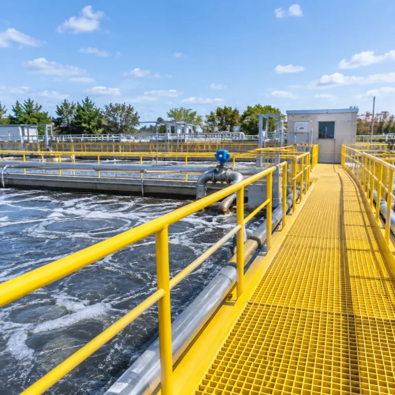
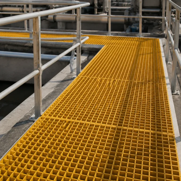
Integrated Support Structures: We frequently pair our structural beams with dedicated frp grating for chemical plant environments, creating fully non-metallic, maintenance-free catwalks, pipe racks, and equipment support frames.
Secondary Containment: Ideal for framing over containment dikes where metal supports would degrade from chemical spills.
Marine and Offshore Infrastructure
Saltwater environments quickly break down conventional carbon steel and rot treated timber. Our fiberglass I-beam designs provide long-term structural resistance against saltwater immersion, salt spray, and extreme UV exposure.
Docks, Piers, and Marinas: Structural stringers and sub-deck support beams that resist marine borers, rot, and saltwater corrosion.
Offshore Platforms: Significant weight savings reduce topside loads while providing high load bearing performance under wind and wave action.
Splash Zone Construction: Zero rust bleed, eliminating the continuous need for scraping, sandblasting, and protective repainting.
Cooling Towers, Walkways, and Industrial Platforms
High-moisture settings and elevated work zones require reliable structural integrity combined with easy handling. Across modern industrial facilities, our pultruded fiberglass beams streamline construction and ensure safe operations.
Cooling Tower Frameworks: Permanent resistance to continuous water spray, biological growth, and chemical water treatments.
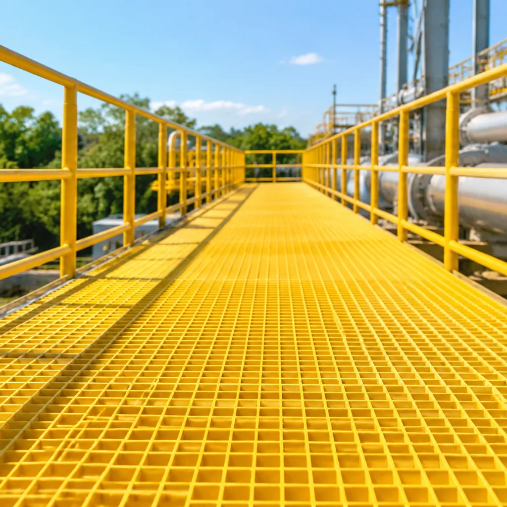
Industrial Walkways and Mezzanines: Exceptional strength-to-weight ratios make transporting and assembling elevated access platforms straightforward without heavy crane equipment.
Electrically Hazardous Areas: Non-conductive structural profiles ensure personnel safety around substations, rail transit systems, and high-voltage power generation units.