FRP Grating Load Tables Load Capacity and Span Guide
Explore FRP grating load tables covering load capacity deflection support spans panel types and RFQ selection for safe efficient design
Understanding FRP Grating Load Tables
What Is an FRP Grating Load Table?
An FRP grating load table is an engineering reference guide that defines the structural capacity of fiberglass-reinforced plastic flooring panels under specific stress conditions. It correlates panel depth, clear span distances, and applied weights with resulting deflection rates.
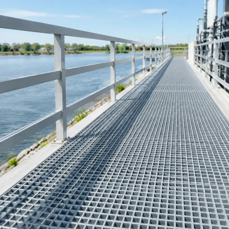
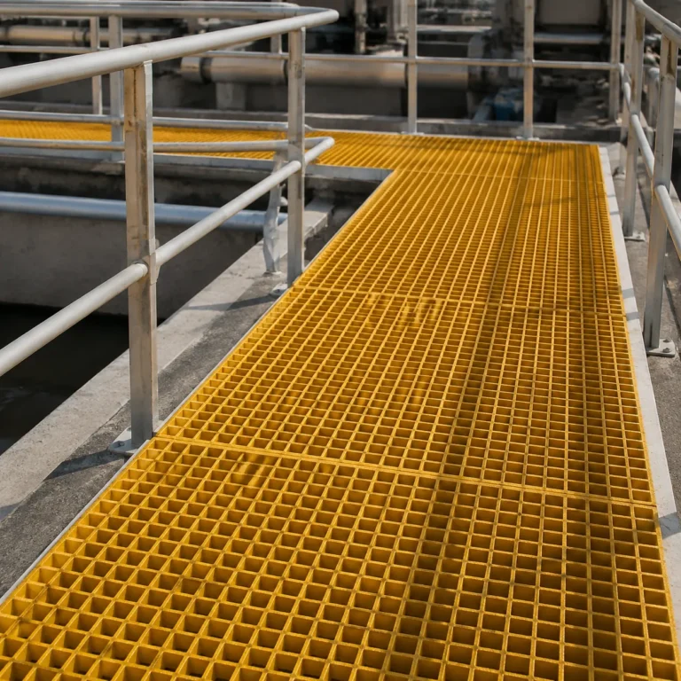
These tables provide verified benchmarks for both molded fiberglass grating and pultruded frp grating, allowing structural engineers, facility managers, and contractors to select appropriate panel profiles for walkways, platforms, trench covers, and structural flooring.
Why Load Capacity and Span Calculations Matter
Accurate load calculations prevent mechanical failure, ensure workplace safety, and prevent unnecessary material costs. Relying on accurate span data provides distinct structural advantages:
Structural Integrity: Ensures the flooring withstands static and dynamic weights without exceeding yield stress limits.
Worker Safety and Comfort: Minimizes trampoline effects and excessive panel flex, which can cause trips, slips, or worker fatigue.
Equipment Protection: Supports heavy rolling carts, machinery, or maintenance gear across the designated span without permanent deformation.
Cost Efficiency: Eliminates over-engineering by matching exact panel thickness and support layouts to real-world requirements.
Key Panel Specifications Affecting Load Performance
Panel geometry and manufacturing processes directly dictate load-bearing capabilities. The most critical variables include:
Specification Structural Role Performance Impact
Manufacturing Process Molded vs. Pultruded Molded provides bi-directional load support; pultruded delivers higher uni-directional strength over longer spans.
Panel Depth / Height Vertical section modulus Increasing panel depth dramatically reduces deflection under a heavy uniform load.
Mesh Pattern Open area and bar distribution Tighter mesh patterns distribute concentrated wheel and foot loads across multiple load-bearing bars.
Bar Thickness Cross-sectional area Thicker web and flange designs resist shear loads and localized point impacts.
Resin Formulation Matrix binding and stiffness Premium resin systems maintain flexural modulus in corrosive, wet, or high-temperature operating conditions.
Core Terminology in FRP Grating Load Ratings
Reading an engineering chart requires speaking the same language as the structural team. When evaluating our load tables, misinterpreting a metric can lead to underspecifying a platform or adding unnecessary structural steel. Here are the core metrics you must know before sizing your panels.
Clear Span vs. Overall Span
A frequent mistake during grating layout is confusing total panel dimensions with the actual unsupported distance:
Clear Span: The open, unsupported distance measured between the inside faces of two structural supports. This is the exact measurement we use in all engineering calculations because it determines bending stress and maximum deflection.
Overall Span: The total physical length of the grating panel from edge to edge, including the portions resting flat on the structural framework.
Always use the clear span when looking up values in our tables. Sizing grating based on the overall panel length instead of the clear distance between supports will give you inaccurate deflection values and lead to over-engineering.
Uniform Load (U) vs. Concentrated Point Load (C)
Different operational environments apply stress across floor panels in distinct ways. Our tables break capacity down into two primary load profiles:
Uniform Load (U): Weight distributed evenly across the entire surface area of the panel, measured in pounds per square foot (psf) or kilonewtons per square meter (kN/m²). This models general foot traffic, standing fluids, or bulk materials spread across walkways.
Concentrated Point Load (C): A heavy, localized force applied directly to a small, specific contact area (typically rated across a 12-inch by 12-inch contact zone). This represents high-stress points like maintenance jacks, heavy machinery legs, or small industrial carts.
For heavy equipment corridors, calculating an accurate FRP grating load capacity based on concentrated wheel loads is critical to preventing permanent structural fatigue.
Bearing Bar Orientation and Load Distribution
How grating carries weight depends entirely on its manufacturing geometry:
Pultruded FRP Grating: Features continuous, high-strength I-bars or T-bars running in one direction. These bearing bars carry the structural load, meaning the panel must be installed with the primary bars bridging directly across the support steel.
Molded Fiberglass Grating: Built with a continuous, interwoven square or rectangular mesh matrix. It provides bidirectional load distribution, allowing panels to support traffic equally in both orientations and simplifying field cutting around pipe penetrations.
FRP Grating Deflection Criteria and Safety Limits
Deflection measures how much an FRP panel bends under structural stress before it returns to its original flat profile. While fiberglass offers tremendous resilience and returns to shape without permanent deformation, uncontrolled bending creates psychological discomfort, equipment instability, and tripping hazards. Balancing allowable deflection with adequate structural safety factors ensures our installations remain secure, compliant, and durable throughout their operating life.
Standard Deflection Limits (L/100, L/150, and L/200)
Structural engineers calculate allowable deflection by dividing the clear span (L) between structural supports by an industry-standard deflection factor:
L/100: Primarily applied to non-critical industrial utility platforms or rough maintenance catwalks where foot traffic is infrequent and noticeable flex causes no operational issues.
L/150: A standard industrial baseline for secondary access walkways, offering moderate stiffness under both concentrated load and uniform load conditions without excessive panel movement.
L/200 (or 0.25 inches / 6.4 mm max): The preferred commercial and heavy industrial standard. We recommend this threshold for continuous pedestrian pathways, battery rooms, and processing areas to prevent worker fatigue and eliminate the perception of structural instability.
Deflection Standard Ratio Max Recommended Deflection (on 36″ Span) Primary Application
Utilitarian / Light L/100 0.36 in (9.1 mm) Rare maintenance access
General Industrial L/150 0.24 in (6.1 mm) Standard platforms and staging
Walkway Comfort Standard L/200 0.18 in (4.5 mm, capped at 0.25 in) Main corridors and public facilities
Deflection Thresholds for Pedestrian vs. Vehicular Traffic
Different types of transit place entirely different dynamic demands on both molded fiberglass grating and high-load pultruded systems:
Pedestrian Foot Traffic: Walking comfort requires strict deflection control. Human perception registers even small drops underfoot, so limiting total deflection to 0.25 inches (6.4 mm) or L/200 is essential. A rigid, stable deck prevents trips, slips, and unnecessary fatigue during daily shifts.
Vehicular and Rolling Loads: Forklifts, pallet jacks, and heavy service carts generate substantial dynamic point loads and rolling impact. Here, deflection must be tightly restricted to protect panel cross-rods and bearing bars from localized shear stress. For heavy rolling transit, we engineer designs around maximum allowable deflections between L/200 and L/250 to avoid premature mechanical wear. Evaluating proper FRP grating panels selection ensures your depth and bar profile match these rolling load profiles.
Long-Term Environmental Factors Affecting Grating Deflection
Static load calculations only tell part of the story. Real-world operating environments influence the flexural modulus and sustained stiffness of composite resins over time:
Thermal Softening: Elevated temperatures soften the resin matrix, reducing the composite’s flexural rigidity. In high-heat areas, panels deflect more under the same load than they do at ambient shop temperatures.
Continuous Sustained Loads (Creep): Placing permanent machinery, heavy tanks, or static inventory on grating induces material creep. Sustained dead loads must be calculated well below the short-term deflection limit to avoid gradual sagging.
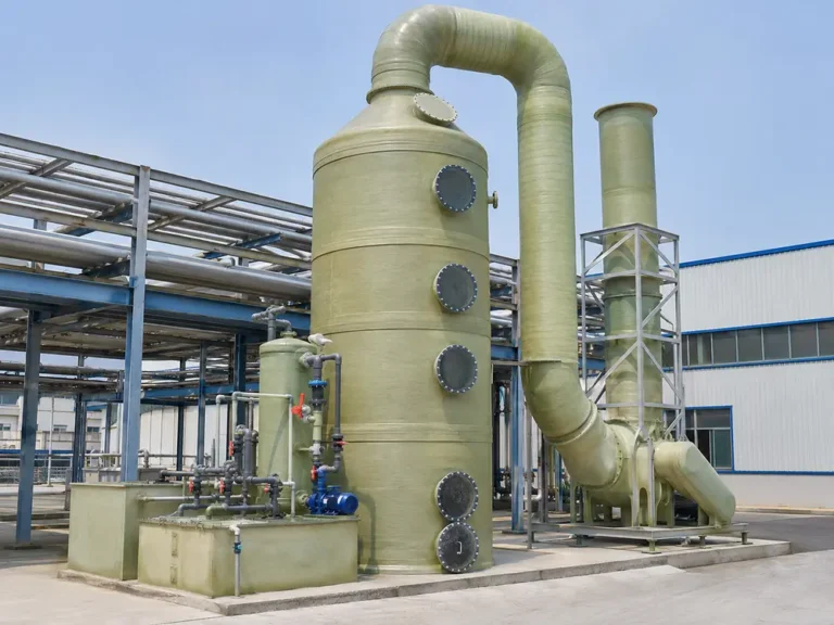
Chemical Saturation: Harsh chemical splashes, hot vapors, and standing acids can soften resin bonds if the chemical exposure profile is misaligned with the resin formulation. Following proactive care and maintenance of FRP grating prevents chemical ponding and guarantees that panels maintain their rated load-bearing stiffness over decades.
Molded vs. Pultruded FRP Grating Load Tables
Evaluating load performance starts with recognizing the structural difference between molded and pultruded designs. Each manufacturing process arranges reinforcing glass fibers differently, creating distinct load distribution behaviors across a given clear span.
Molded FRP Grating: Bi-Directional Load Capabilities
Our molded fiberglass grating is cast in a single-piece mold with continuous interwoven glass fibers running in both directions. This creates a bidirectional load-bearing structure.
Uniform strength: Withstands stresses equally along both the length and width of the panel.
On-site cutouts: Pipe penetrations and structural cutouts can be made without requiring additional sub-framing or sacrificing general structural stability.
Impact tolerance: Natural flex properties distribute repeated impacts across the entire square mesh grid, lowering localized stress concentrations.
Pultruded FRP Grating: High-Strength Uni-Directional Load Tables
For longer spans and heavier weight requirements, our pultruded frp grating delivers higher stiffness. Pultrusion pulls continuous glass rovings and mats through a heated die, packing roughly 65% to 70% glass content into the bearing bars.
High strength-to-weight ratio: Bearing bars carry the majority of the weight in one direction, significantly increasing safe uniform load limits.
Longer spans: Provides minimal deflection over wide support centers compared to molded alternatives of the same depth.
Profile versatility: Available in I-bar and T-bar shapes to balance open area percentages with structural stiffness.
Load Capacity Comparison by Panel Thickness and Mesh Pattern
The table below outlines typical industrial design parameters, comparing panel configurations over common support configurations at an allowable deflection limit of L/100:
Grating Profile Standard Depth Mesh Pattern / Open Area Max Clear Span Allowable Uniform Load Typical Application
Molded Square Mesh 25 mm (1.0″) 38 x 38 mm (70% open) 600 mm (24″) 5.0 kN/m² Light pedestrian walkways, catwalks
Molded Square Mesh 38 mm (1.5″) 38 x 38 mm (70% open) 900 mm (36″) 7.5 kN/m² Standard industrial flooring, trench covers
Molded Mini-Mesh 38 mm (1.5″) 19 x 19 mm (42% open) 900 mm (36″) 10.0 kN/m² Barefoot walkways, small tool-drop zones
Molded Square Mesh 50 mm (2.0″) 50 x 50 mm (78% open) 1200 mm (48″) 12.0 kN/m² Heavy maintenance platforms, wet sumps
Pultruded I-Bar (I-60) 38 mm (1.5″) 60% open 1200 mm (48″) 15.5 kN/m² Long-span platforms, heavy pedestrian traffic
Pultruded T-Bar (T-50) 50 mm (2.0″) 50% open 1500 mm (60″) 22.0 kN/m² Equipment access spans, heavy cargo areas
Standard Depth Selection: A 38 mm (1.5″) depth serves as the industry standard for walking platforms across 900 mm clear spans.
Span Deflection Limits: When your structural framing exceeds a 900 mm span, shifting from molded mesh to a pultruded profile controls deflection without requiring deeper structural support steel.
FRP Grating Support Span Guide
Selecting the correct support spacing keeps your flooring safe, rigid, and compliant with safety codes. We design our grating systems to balance structural stiffness with material efficiency, ensuring minimal flex under operational traffic.
Recommended Support Spans by Panel Depth and Type
The allowable clear span depends heavily on panel depth and manufacturing method. Pultruded profiles handle longer runs due to high longitudinal glass content, whereas molded panels deliver equal strength in both directions across moderate spans.
The table below outlines our recommended support spans for standard industrial walkways under a typical pedestrian design load:
Panel Depth Grating Construction Standard Mesh / Bar Spacing Recommended Clear Span Maximum Clear Span
25 mm (1.0 in) Molded fiberglass grating 38 x 38 mm 600 mm (24 in) 750 mm (30 in)
38 mm (1.5 in) Molded fiberglass grating 38 x 38 mm 900 mm (36 in) 1050 mm (42 in)
50 mm (2.0 in) Molded fiberglass grating 50 x 50 mm 1200 mm (48 in) 1350 mm (54 in)
25 mm (1.0 in) Pultruded FRP grating I-6010 / I-6015 900 mm (36 in) 1100 mm (43 in)
38 mm (1.5 in) Pultruded FRP grating I-6015 / T-5015 1200 mm (48 in) 1500 mm (60 in)
50 mm (2.0 in) Pultruded FRP grating I-6020 / T-5020 1500 mm (60 in) 1800 mm (71 in)
Key engineering rules for selecting your span: Pedestrian walkways: Keep deflections below 6.4 mm (0.25 in) to maintain walking comfort and eliminate the perception of bounce. Heavy-duty and rolling loads: Reduce support spans by 30% to 50% compared to standard pedestrian walkway values to prevent fatigue at panel joints.
Minimum Bearing Support Requirements
Proper seat width guarantees that loads transfer safely to the substructure without crushing the grating edges or causing localized shear failure:
Structural Support Width: We require a minimum of 40 mm (1.5 in) of direct bearing on steel beams or concrete ledges. For spans exceeding 1000 mm, increase bearing width to 50 mm (2.0 in).
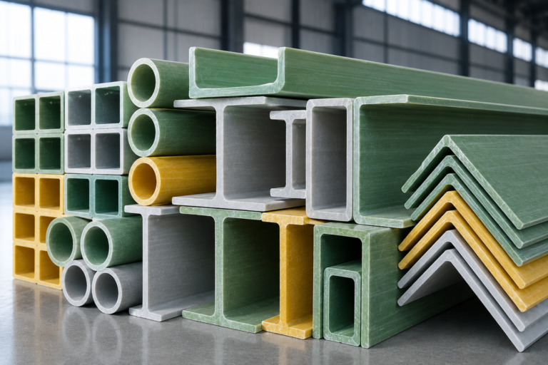
Support Substructures: Ensure the supporting framework, such as structural FRP pultruded profiles or structural steel channels, provides flat, continuous, and level surfaces.
Mechanical Fasteners: Secure panels to supports using stainless steel M-clips, G-clips, or saddle assemblies. Use a minimum of 4 clips per panel or space them roughly every 1.0 to 1.2 linear meters along the support members.
Continuous vs. Simple Span Configurations
How you lay panels across structural supports directly changes load-bearing performance and total deflection:
Simple Span (Single Span): The panel rests across only two supports. This layout results in maximum mid-span deflection and the lowest allowable uniform load. It is common in trench covers and access hatches where single removable panels are mandatory.
Continuous Span (Multi-Span): The panel extends over three or more supports. Multi-span installations cut mid-span deflection by up to 40% to 50% compared to a simple span with the exact same clear span distance and load.
Whenever project layouts allow, specify continuous spans to gain greater structural rigidity, lower panel deflection, and reduce the total number of required structural framing supports.
How to Read and Use an FRP Grating Load Table
Reading engineering data sheets does not need to be complicated. We design our FRP grating load tables to help you quickly match structural demands with the correct panel profile. Follow these three practical steps to evaluate your requirements accurately.
Step 1: Determine Span Distance and Grating Depth
First, measure the exact clear span between your support beams or structural framework. Never use center-to-center distances, as load calculations rely strictly on the unsupported gap.
Measure the clear distance: Record the open measurement between structural ledges or FRP grating embed angles.
Select potential panel depths: Standard depths typically range from 25 mm (1.0 in) to 50 mm (2.0 in) depending on whether you install molded fiberglass grating or high-span pultruded frp grating.
Verify bearing width: Ensure both ends have adequate bearing surface across the support edges before finalizing depth selection.
Step 2: Identify Application Load Requirements
Next, establish the exact nature of the weight passing over the grating surface. Different operational conditions place distinct mechanical stresses on panel ribs.
Uniform Load (U): Measured in kN/m² or lbs/ft² (psf). Use this rating for general foot traffic, storage platforms, and evenly distributed equipment weight.
Concentrated Point Load (C): Measured in kN or lbs. Crucial for heavy point forces like wheeled carts, rolling maintenance equipment, or heavy installations such as an FRP drain cover grating subjected to tire impacts.
Safety Factor: Standard design recommendations apply a 4:1 safety factor for molded profiles and a 3:1 ratio for pultruded profiles against ultimate failure.
Step 3: Cross-Reference Allowable Load and Deflection Values
Locate your measured span along the top row of the load chart, then trace down to find your grating thickness and bar construction. Check the reported deflection under your expected operating load.
Clear Span (mm / in) Panel Depth & Style Design Uniform Load Deflection at Given Load Recommended Limit
600 mm (24 in) 25 mm Molded Mesh 15.0 kN/m² 3.2 mm (0.12 in) Within L/150 limit
900 mm (36 in) 38 mm Molded Mesh 10.5 kN/m² 5.8 mm (0.23 in) Within L/150 limit
1200 mm (48 in) 38 mm Pultruded I-Bar 12.0 kN/m² 5.5 mm (0.22 in) Within L/200 limit
1200 mm (48 in) 50 mm Molded Mesh 8.2 kN/m² 6.0 mm (0.24 in) Within L/200 limit
Always ensure your calculated deflection stays within acceptable comfort and safety thresholds—typically 6.4 mm (0.25 in) or less for pedestrian footpaths—to prevent structural bounce and user fatigue.
How to Select the Right FRP Grating and Prepare an RFQ
Choosing the correct composite panel requires balancing structural capacity, environmental conditions, and long-term operating costs. A complete evaluation ensures that your panels meet load limits while staying within budget.
Selecting Grating by Application and Traffic Type
The intended use dictates whether you require molded fiberglass grating or pultruded frp grating.
Pedestrian Walkways and Platforms: Foot traffic generally demands standard panels engineered to limit deflection to a comfortable threshold under an average uniform load. For typical access walkways and trench covers, our 1-1-2 FRP grating provides an optimal balance of structural rigidity, manageable weight, and cost.
Rolling Carts and Maintenance Equipment: Light wheeled loads need panels with higher stiffness and smaller mesh apertures to prevent wheel drop and excessive flexing across the clear span.
Heavy Industrial and Vehicular Traffic: Facilities managing forklifts or truck traffic require high-depth pultruded profiles or thick molded panels engineered to absorb heavy wheel loads without structural breakdown.
Choosing the Right Resin System for Chemical Environments
The resin matrix determines how well the grating resists corrosion, fire, and UV exposure. Matching the resin to the chemical exposure profile is critical:
Orthophthalic Polyester: Suitable for light industrial use, basic water treatment, and standard environments with minimal chemical fumes.
Isophthalic Polyester: Ideal for general industrial plants and coastal outdoor structures exposed to moderate acids, splash zones, and washdown chemicals.
Vinyl Ester: Engineered for severe chemical settings, including acid storage areas, electroplating lines, and heavy petrochemical handling where extreme corrosion resistance is non-negotiable.
Phenolic: Selected specifically for offshore and enclosed marine zones requiring maximum fire resistance and minimal smoke generation.
Essential Information Required for an Accurate FRP Grating RFQ
To ensure our team delivers an accurate technical review and competitive quote, compile the following project details for your RFQ:
Clear Span Dimensions: The unsupported distance between structural steel or concrete supports.
Design Load Profile: Expected load figures, specifying concentrated point loads, rolling wheel weights, or distributed uniform load values.
Allowable Deflection: Your project’s specified deflection threshold (such as L/100, L/150, or L/200).
Environmental Conditions: Operating temperature range, chemical types, concentration levels, and direct UV exposure.
Surface and Finish: Grit tops for wet or oily environments, smooth tops, or covered panels for odor control. You can explore standard options across our complete FRP grating product line.
Panel Takeoffs and Quantities: Total square meters or square feet, standard panel dimensions, or cut-to-size drawing files for factory fabrication.