FRP I Beams Sizes Span Capability and Selection Guide
Explore FRP I Beams sizes span capability load performance corrosion resistance and structural selection for durable lightweight industrial applicatio
What Is an FRP I-Beam? Overview and Key Properties
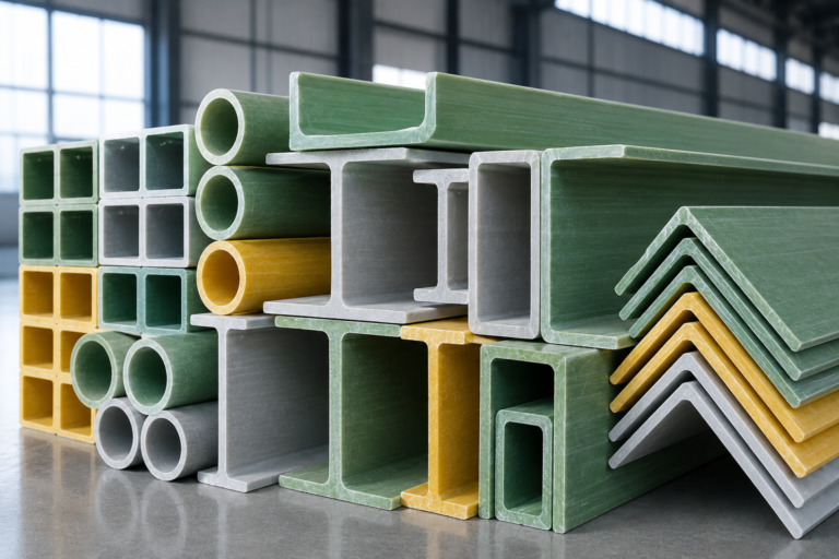
An FRP I-beam is a pultruded structural composite engineered for demanding load-bearing frameworks. Designed as an advanced alternative to traditional structural steel and timber, these beams combine glass fiber reinforcement with specialized thermoset resin systems. The resulting profile provides exceptional mechanical strength while resisting environmental degradation, chemicals, and moisture in severe industrial operating conditions.
Pultrusion Manufacturing Process
Pultrusion is a continuous molding process that guarantees uniform cross-sections and predictable mechanical performance along the entire profile length:
Fiber Reinforcement: High-strength continuous glass fiber rovings provide longitudinal tensile strength, while continuous filament mats supply transverse reinforcement.
Resin Impregnation: The structural fibers pass through a liquid bath of isophthalic polyester or vinyl ester resin, fully saturating the reinforcement core.
Heated Die Curing: Continuous pullers draw the saturated matrix through a precision-machined, heated steel die where the composite polymerizes and cures into its final I-profile shape.
Surface Protection: An integral synthetic surface veil is incorporated to form an outer resin-rich layer that shields against ultraviolet degradation, corrosion, and fiber blooming.
Key Mechanical and Structural Properties
Pultruded structural profiles exhibit directional strength tailored for structural engineering requirements:
High Strength-to-Weight Ratio: Delivers structural rigidity comparable to steel at roughly one-quarter the weight of carbon steel shapes.
Corrosion Resistance: Immune to rust, rot, chemical immersion, and saltwater attacks, eliminating regular recoating or galvanizing cycles.
Dielectric Insulation: Completely non-conductive both electrically and thermally, improving workplace safety in power-sensitive facilities.
Impact Resilience: Withstands high cyclic loads and local point deflections without taking a permanent structural set.
FRP I-Beam vs. H-Beam Structural Profiles
Selecting between an FRP I-beam and a wide-flange H-beam depends on the project’s primary axis load dynamics:
Feature FRP I-Beam Profile FRP H-Beam (Wide Flange)
Flange Proportion Flange width is narrower than the overall web depth Flange width is typically equal or close to the web depth
Primary Loading Axis Optimized for major-axis flexure and unidirectional bending Designed for heavy column loading and biaxial bending
Lateral Torsional Resistance Moderate; best suited for supported floor joists and rafters High; offers superior resistance to lateral-torsional buckling
Common Application Secondary beams, platform stringers, and structural purlins Primary columns, heavy portal framing, and large equipment bases
Standard FRP I-Beam Sizes and Dimensions
We engineer pultruded structural profiles to match the dimensional standards required for modern industrial frameworks. Standard FRP I-beam profiles deliver a direct replacement option for traditional steel sections, maintaining standard heights and widths while cutting structural dead weight.
Common Metric and Imperial Sizes
Our production lines stock standard structural dies in both imperial and metric sizes. The table below lists the most common profile cross-sections used in load bearing support frameworks:
Imperial Size (Depth x Flange) Metric Equivalent (d x b_f) Web / Flange Thickness (t_w / t_f) Typical Applications
4″ x 2″ 102 mm x 51 mm 1/4″ (6.4 mm) Light equipment supports, handrail kickers
6″ x 3″ 152 mm x 76 mm 1/4″ (6.4 mm) Secondary walkway stringers, platforms
8″ x 4″ 203 mm x 102 mm 3/8″ (9.5 mm) Primary walkways, tank supports
10″ x 5″ 254 mm x 127 mm 1/2″ (12.7 mm) Structural deck framing, pipe rack bents
12″ x 6″ 305 mm x 152 mm 1/2″ (12.7 mm) Heavy industrial platform main beams
Flange and Web Dimension Specifications
The geometry of an FRP I-beam relies on three critical elements:
Total Depth (d): Governs vertical stiffness and overall bending capacity under downward loading.
Flange Width (b_f): Provides lateral stability and prevents premature torsional buckling under long spans.
Web and Flange Thickness (t_w, t_f): Pultruded beams maintain a uniform cross-section throughout their length. The reinforced junction between the web and flange includes a generous radius to distribute shear stress evenly.
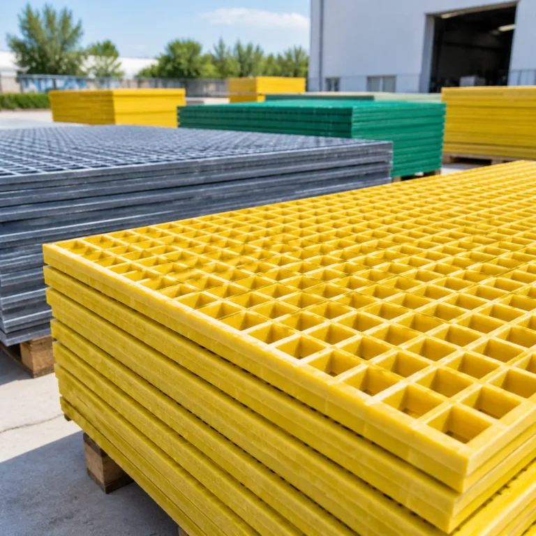
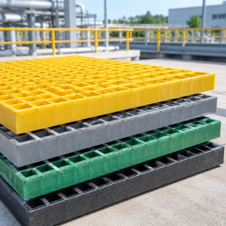
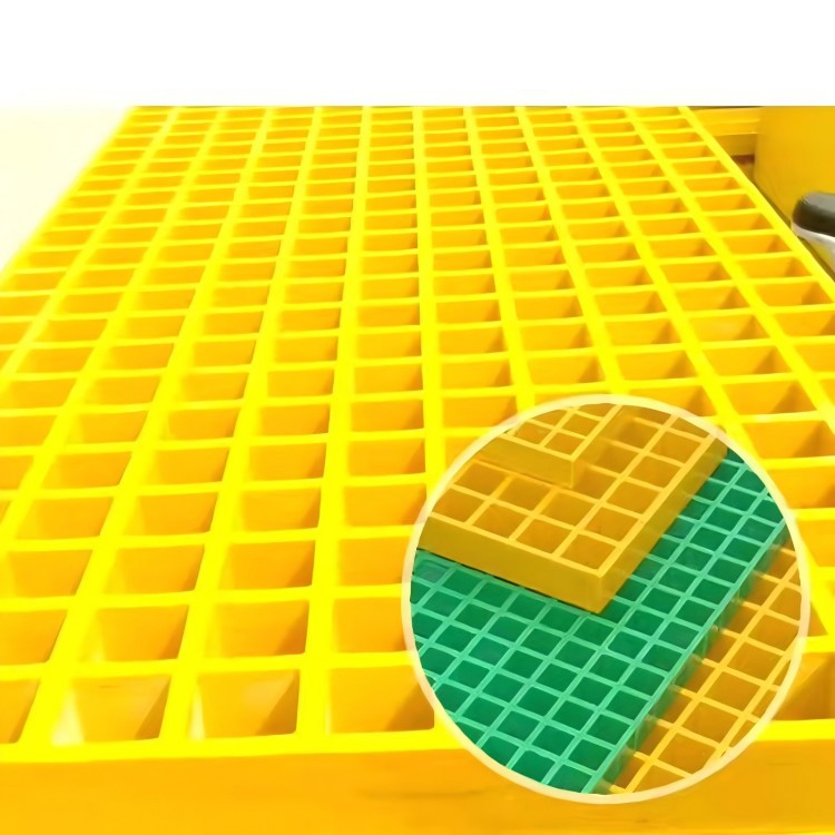
When designing modular floor layouts, pairing your beam sizing with the right FRP grating standard size simplifies framing layouts and cuts down on secondary clip installations.
Weight per Meter and Section Properties
Every fiberglass beam delivers exceptional structural rigidity at roughly 25% the density of steel. Key engineering properties for calculating deflections and sizing beam spans include:
Profile Size (in) Nominal Weight (kg/m) Nominal Weight (lb/ft) Area A (in²) Moment of Inertia Ix (in⁴) Section Modulus Sx (in³)
4 x 2 x 1/4 2.85 1.91 1.88 4.80 2.40
6 x 3 x 1/4 4.46 3.00 2.88 17.50 5.83
8 x 4 x 3/8 8.78 5.90 5.72 61.20 15.30
10 x 5 x 1/2 14.88 10.00 9.50 160.00 32.00
12 x 6 x 1/2 17.86 12.00 11.50 284.00 47.33
These section properties form the baseline for sizing beam spans and confirming maximum serviceability deflections under design loads.
FRP I-Beam Span Capability and Load Performance
Understanding how a fiberglass beam performs under load is essential for ensuring structural integrity in demanding environments. Unlike traditional steel, where structural design is primarily governed by yield strength, designing with composite beams requires evaluating both mechanical strength and serviceability limits. Our load bearing beams provide predictable performance across various spans when sized according to proper structural criteria.
Allowable Uniform and Point Load Limits
We evaluate span capability by analyzing how a profile carries both uniformly distributed loads (UDL) and concentrated point loads:
Uniformly Distributed Loads (UDL): Spreads weight evenly along the total clear span. This is typical for platform support beams carrying grating panels or continuous equipment setups.
Point Loads: Applies force at a single concentrated location, such as mid-span. Point loads generate higher local shear stresses and peak bending moments, requiring either deeper beam depths or reduced span lengths.
Span-to-Depth Ratio: We recommend maintaining an optimal span-to-depth ratio between 15:1 and 20:1 for standard structural framing to balance load resistance and profile efficiency.
When pairing these profiles into larger framing systems, reviewing our guide on frp pultruded profiles resin types shapes and structural selection guide helps match beam geometry to your operational loads.
Load Condition Key Stress Focus Primary Failure Check Design Recommendation
Uniform (UDL) Longitudinal Bending Deflection Limit Optimize span-to-depth ratio
Mid-Span Point Peak Flexural & Shear Web Shear & Deflection Add stiffeners or reduce clear span
Moving Load Dynamic Impact & Fatigue Serviceability & Fastener Wear Incorporate dynamic impact factors
Deflection Criteria and Serviceability Limits
For most pultruded structural profiles, deflection—rather than ultimate breaking strength—governs design limits. Composite materials have a lower modulus of elasticity compared to carbon steel, meaning the beam will flex before it reaches its flexural breaking limit.
We design and verify load performance against standard serviceability criteria:
L/180: Common threshold for secondary support structures, pipe racks, and areas where visual sag does not impair operations.
L/240: Recommended standard for industrial walkways, pedestrian platforms, and access stairs to prevent user discomfort.
L/360: Strict serviceability limit applied where equipment sensitivity, brittle finishes, or mechanical machinery require minimal movement.
Using a conservative safety factor between 2.5 and 3.0 against ultimate flexural failure ensures your installation remains well within safe operational limits throughout its service life.
Flexural Strength and Web Buckling Factors
Longitudinal tensile and compressive strengths run parallel to the continuous roving reinforcement in our beams, giving them exceptional flexural capacity along their primary axis. However, full structural evaluation must also account for localized web stresses:
Web Buckling and Crippling: High concentrated loads applied directly over narrow support bearings can cause localized web crushing. We recommend bearing plates or vertical web stiffeners at primary support points to distribute bearing stresses safely.
Lateral Torsional Buckling: Deep, narrow-flange I-beams subjected to long unsupported spans can twist under high compressive bending loads. Installing intermediate lateral bracing or tie-bars on long runs stabilizes the compression flange.
Shear Modulus Considerations: Because composite profiles exhibit distinct shear properties, beam deflection calculations must account for both pure bending strain and shear deformation, especially on shorter spans with high depth-to-span ratios.
Key Advantages of Fiberglass I-Beams
Pultruded structural profiles solve critical engineering challenges where conventional building materials fall short. When we design and supply an FRP I-beam, we focus on delivering dependable load-bearing performance in environments that rapidly degrade steel, concrete, or wood.
Superior Corrosion and Chemical Resistance
Industrial facilities often expose framing to aggressive chemical vapors, acidic washdowns, and persistent moisture. Unlike carbon steel or aluminum, a fiberglass beam will not rust, rot, or pit when subjected to harsh reagents.
Chemical immunity: Withstands continuous exposure to acids, alkalis, and industrial solvents.
Moisture resistance: Impermeable to salt spray and humidity, making it ideal alongside specialized layouts like chemical plant structural installations.
No protective coating needed: The corrosion resistance extends throughout the entire composite matrix, eliminating the need for periodic repainting or galvanizing.
High Strength-to-Weight Ratio
Our pultruded fiberglass beams deliver the structural stiffness needed for heavy-duty framing while weighing roughly 75% less than structural steel shapes of equivalent depth.
Material Profile Approximate Weight Density Field Handling Needs
Pultruded FRP I-Beam ~1,800 kg/m³ Manually maneuverable on site; minimal crane time
Structural Carbon Steel ~7,850 kg/m³ Requires heavy lifting equipment and dedicated riggers
Treated Structural Timber ~600–900 kg/m³ Variable strength; degrades with moisture uptake
This lightweight profile lowers dead-weight structural calculations, streamlines site transport, and cuts erection labor substantially.
Electrical and Thermal Non-Conductivity
Safety in utility and heavy industrial installations depends on isolating electrical current and mitigating heat transfer:
Dielectric safety: Excellent non-conductive properties eliminate touch-potential hazards, fitting critical criteria such as electrical substation safety protocols.
EMI/RFI transparency: Does not interfere with radar, radio frequencies, or sensitive instrumentation.
Thermal insulation: Dramatically limits thermal bridging compared to metal framing, reducing condensation issues in temperature-controlled spaces.
Long Service Life with Low Maintenance
Fiberglass structural beams deliver a low total cost of ownership by virtually eliminating routine upkeep. Because the pultruded matrix resists UV breakdown, biological decay, and aggressive washdowns, structural integrity remains consistent over decades of active service without scraping, sandblasting, or chemical re-treatments.
Structural Selection Guide: How to Choose the Right FRP I-Beam
Choosing the correct profile requires balancing structural safety, environmental resilience, and overall system cost. When we guide clients through product selection, we focus on matching specific operating demands directly against the mechanical limits of each beam profile.
Evaluating Span Length and Load Requirements
Proper structural sizing begins with an accurate assessment of all expected loads and allowable service limits:
Identify Load Conditions: Calculate both uniform distributed loads (dead weight, operating weight) and concentrated point loads that the fiberglass beam must carry.
Serviceability Over Ultimate Stress: Unlike steel design, where yield strength often governs, FRP structural design is almost always governed by deflection limits (typically L/240 or L/360).
System Integration: Calculate support intervals based on the complete deck design. For instance, pairing your beam spacing with appropriate heavy industrial FRP grating load capacity ensures that secondary load-bearing members do not exceed permissible deflections.
Safety Factors: Maintain a recommended safety factor between 2.5 and 3.0 on structural spans to account for dynamic vibrations and sustained creep effects.
Assessing Environmental Conditions and Resin Selection
The service environment directly determines the resin matrix required for our pultruded structural profiles:
Isophthalic Polyester: Best suited for standard outdoor infrastructure, light washdown zones, and environments with moderate chemical splash or moisture exposure.
Vinyl Ester: Essential for highly acidic or caustic chemical exposures, marine docks, and battery storage rooms. For facilities operating with aggressive chemical exposure, pairing these beams with chemical plant FRP grating creates an entirely corrosion-proof sub-structure.
UV Protection: For severe solar exposure, specify beams with a synthetic surface veil and integrated UV inhibitors to prevent fiber blooming over extended outdoor service.
Comparing FRP I-Beams with Structural Steel and Wood
The following matrix highlights the operational differences across traditional structural materials:
Performance Metric Pultruded FRP I-Beams Structural Carbon Steel Treated Structural Timber
Corrosion Resistance Excellent (Acids, salts, caustics) Poor (Requires continuous recoating) Moderate (Prone to rot and insects)
Weight per Volume Approx. 75% lighter than steel Heavy (Demands heavy cranes) Moderate
Electrical Safety Non-conductive Highly conductive Non-conductive when dry
Installation Speed Fast (Standard hand-tool cutting) Slow (Welding and hot-work permits) Fast
Long-Term Maintenance Virtually zero maintenance High (Blasting, painting, rust control) High (Chemical treatments, sealing)
Lifecycle Cost Lowest over extended operation High due to upkeep and downtime Moderate to high due to decay
Common Applications of FRP I-Beams
We manufacture and supply FRP I-beams to solve severe corrosion and weight challenges across demanding sectors. Where structural steel corrodes and treated timber rots, our composite beams deliver reliable structural capacity with zero rust. From primary load-bearing frameworks to secondary equipment supports, these beams provide an engineered, long-term alternative in harsh industrial environments.
Chemical Processing and Wastewater Facilities
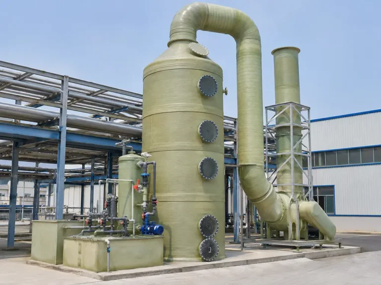
Corrosive airborne vapors, continuous moisture, and aggressive chemicals quickly break down standard carbon steel. We deploy pultruded structural profiles to maintain load-bearing performance throughout challenging environments like pickling lines, battery plants, and municipal treatment works.
Fume and Spill Resistance: Withstands continuous exposure to acids, alkalis, and chlorides without pitting or section loss.
Basin and Tank Framing: Ideal for clarifier covers, sludge processing decks, and structural supports across corrosive industrial facilities.
Zero Repainting: Eliminates regular sandblasting, painting, and maintenance shutdowns.
Marine and Offshore Infrastructure
Saltwater spray, UV radiation, and continuous wave action make marine environments extremely destructive to metals. We engineer our fiberglass beam products to withstand constant exposure to harsh coastal elements without degrading.
Piers, Docks, and Wharves: Provides reliable framing beneath decks exposed to tides and saltwater spray.
Offshore Platforms: Reduces topside dead weight while resisting ocean breezes and chemical splash zones.
Washdown Areas: Holds up under high-pressure saltwater cleaning and heavy daily use.
Cooling Towers, Walkways, and Industrial Platforms
High humidity, circulating water, and biocide treatments create a continuously wet environment that rapidly deteriorates structural steel and timber framing inside cooling towers. Our FRP I-beams serve as reliable, non-rotting skeletal framing that keeps cooling systems running safely.
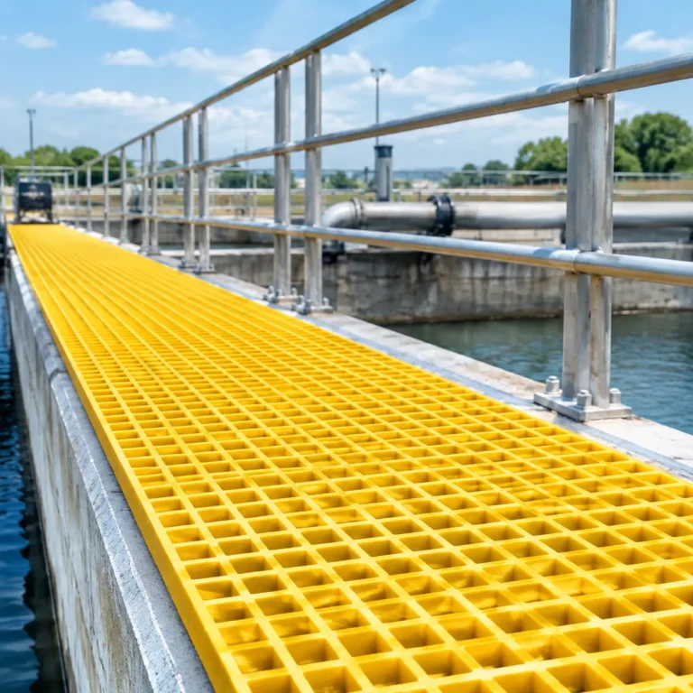
For elevated walkways, access mezzanines, and stair towers, these beams integrate smoothly with structural grating and FRP grating embed angles to establish safe, non-conductive access platforms for plant operators. They install easily with basic tools and deliver reliable performance in damp, demanding industrial plants.